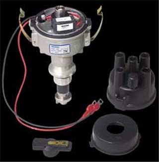
All new Wisconsin multi-cylinder engines are now being equipped with a solid state ignition distributor. Externally the new solid state ignition distributors are similar in appearance to a conventional point ignition distributor. Internally the major differences are;
1) Distributor cam which opens ignition points has been replaced
with a magnet assembly.
2) Ignition points have been replaced with a "Hall effect
type" electronic module.
This solid state ignition distributor uses two primary leads which attach to the ignition coil. The black or blue lead connects to the negative (-) terminal of the ignition coil while the red lead connects to the positive (+) side of the ignition coil.
NOTE: The same Wisconsin ignition coil is used on the solid state and point ignition systems. Be aware that this coil has an internal resistor and many aftermarket do not have these feature even though in outward appearance, they look the same.
Our specialty in this area is all parts for all distributor's installed on Wisconsin and Continental engines over the years. However recently we have expanded these offerings to cover replacement parts and complete magneto's for all engine brands. Go here for a partial list.
We can also supply replacement distributors and parts for the ssi distributors used on all current Wisconsin engines.
The following steps should be performed if the engine's ignition system appears to not be operating properly:
1) Visually inspect all plug wires, coil wire, distributor cap and rotor. replace any components that show deterioration. It is especially important that the cap and plug wires be in good condition free of oil, grease and moisture. If wire has a slight cut or nick in it some people put a couple of turns of electrical tape around the wire. This has not effect. To have the proper "dielectric strength" (resistance for current to travel through an object such as electrical tape), you would need to have a couple of inches of tape wrapped around the cut. Replace the wire.
2) Check for loose or poor connections in the ignition circuit. Check battery terminals for corrosion and loose connections.
3) Check battery's voltage with the engine off. It should be between 12 - 15 volts.
NOTE: The ignition timing adjustment specifications and procedures for the sold state ignition systems are the same as the corresponding point ignition distributor. An automotive type timing light should be used to check and adjust the ignition timing.
Testing can be done either with a voltmeter or a 12 volt test light.
VOLTMETER TESTING
1) Connect the positive (+) lead of a voltmeter to the negative
(-) side of the ignition coil. Ground the negative (-) lead of
the voltmeter. Set the volt meter to DC volts on at least 15 volt.
2) Disconnect the high voltage wire from the center of the distributor
cap and ground it to the engine block or frame of the equipment.
3) Crank engine.
4) The voltmeter should fluctuate from a range of 1 - 2 volts
to a range of 10 - 12 volts as the engine is cranked.
NOTE: On some voltmeters the needle will appear to bounce between
1 - 12 volts.
5) If the voltmeter does not fluctuate, one of the following problems
exist:
a) If the voltmeter shows a constant "0"
reading, there is an open circuit somewhere in the primary ignition
circuit.
b) If the voltmeter shows a constant voltage in the 1.0 - 3.5
volt range, the electronic module is shorted out.
c) If the voltmeter shows a constant voltage equal to the battery
voltage, the electronic module has an open circuit and requires
replacement.
12v TEST LIGHT
Details to follow
NOTE: To avoid damage to the distributor components the following conditions must be avoided;
1) REVERSE
POLARITY - Do not reverse
the main battery cables or the wires from the distributor to the
coil even for a second. This distributor is negative ground only.
The black coil lead goes to the negative (-) terminal of the coil;
the red lead goes to the (+) terminal of the coil.
Some early production distributors have a blue lead instead of
a black lead for the negative coil lead.
2) VOLTAGE SURGES - Do not operate the engine with the battery disconnected. Insure all electrical connections are made properly. Avoid using switches on the engine which cause excessive arcing.
3) ALWAYS DISCONNECT the battery ground (negative) cable when charging the battery.
4) JUMP STARTING - Only use another 12 volt battery for jump starting. Be sure the battery polarity is correct (positive to positive, negative to negative).
NOTE: A HIGH AMPERAGE BOOST CHARGE CAN DAMAGE THE SOLID STATE COMPONENTS WITHIN THE DISTRIBUTOR